Skip to content
Menu
Home
About Us
Background
Radiology Equipment
Webmaster & Author
Academics
Radiographic Protocols
Radiography Forum
Academic Staff Research
Profile
Lost Password
More
Microsoft Office 365
OT Calling Form
Login
Membership
AskRadiographer Knowledgebase
All Categories
CT Scan - Body Region
MRI - Spine Region
Computed Tomography
Magnetic Resonance Imaging
MRI - Lower Limb Region
MRI - Head Region
ANGIOGRAPHY - OTHERS
MRI - Body Region
CT Scan - Others
Angiography - Body Region
CT Scan - Head Region
CT Scan - Upper Limb Region
Mammogram
Popular Search
cta
mri
the
ctv
cta brain
View Categories
Home
KB
Computed Tomography
CT Scan - Head Region
HRCT TEMPORAL BONE NON CONTRAST
Last Updated on January 21, 2023 by
Mohamad Izwan
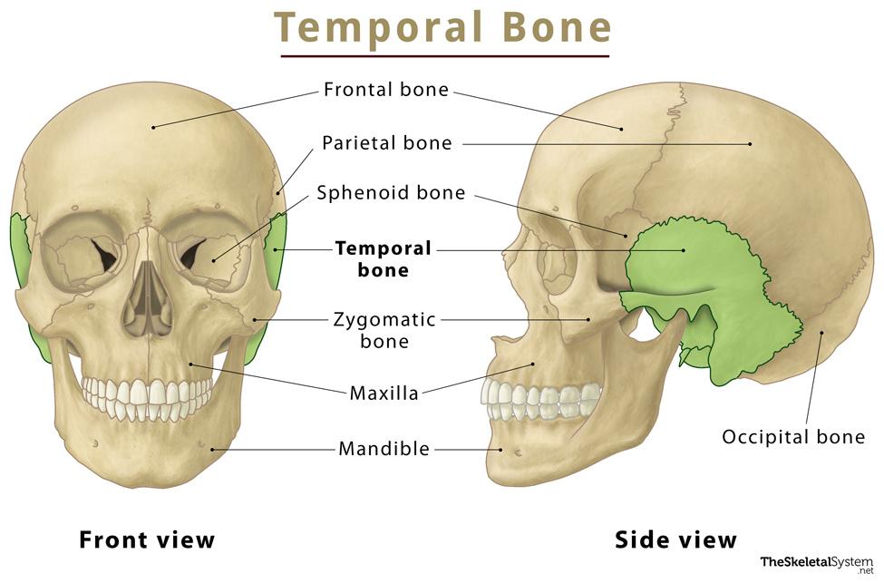
Anatomy of Temporal Bone
Image taken from The Skeletal System.net
Appearance of HRCT TEMPORAL BONE NON CONTRAST Images
Examination Overview
Protocol Structure
00_Inner Ear (Adult)
Topogram
Non Contrast (vertex skull to the mid mandible)
Topogram
Position the patient in head first supine position.
Align the patient in Mid-Sagittal plane of the table.
Position the transverse laser light beam at the vertex of skull to start the topogram.
Head rest must in flat.
Topogram Parameters
Topogram length: 256 mm
Slice: 0.6 mm
Scanning direction:
Craniocoudal
Tube position: Lateral
Stop the topogram scanning when the scanning reach / pass over the
mid of mandible
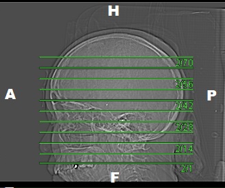
Non Contrast
Plan the Scan FOV (SFOV) box at topogram image
Set the top line at the level upper frontal sinus
Set the bottom line at the level of lower maxillary sinus
Ensure the lateral line to cover patient’s head outline.
Scanning Parameters
kV: 120 kV
mAs:
Tube Current Modulation (TCM)
Scanning Direction:
Craniocaudal
Scan Delay: 2 s
Slice: 2.0mm
Image Comment: –
Pitch: 0.8
Quality Reference mAs : 230
Reconstruction of HRCT Temporal Bone Non Contrast
Series of Images Send to PACS
Topogram 0.6 T80f
InnerEar 2.0 H60s
InnerEar 0.6 H60s
InnerEar 2.0 H30s
InnerEar 0.6 H30s
Patient Protocol
CTA BRAIN
CT BRAIN CONTRAST (IGS PROTOCOL)