Last Updated on January 12, 2023 by Mohamad Izwan
Anatomy of Liver
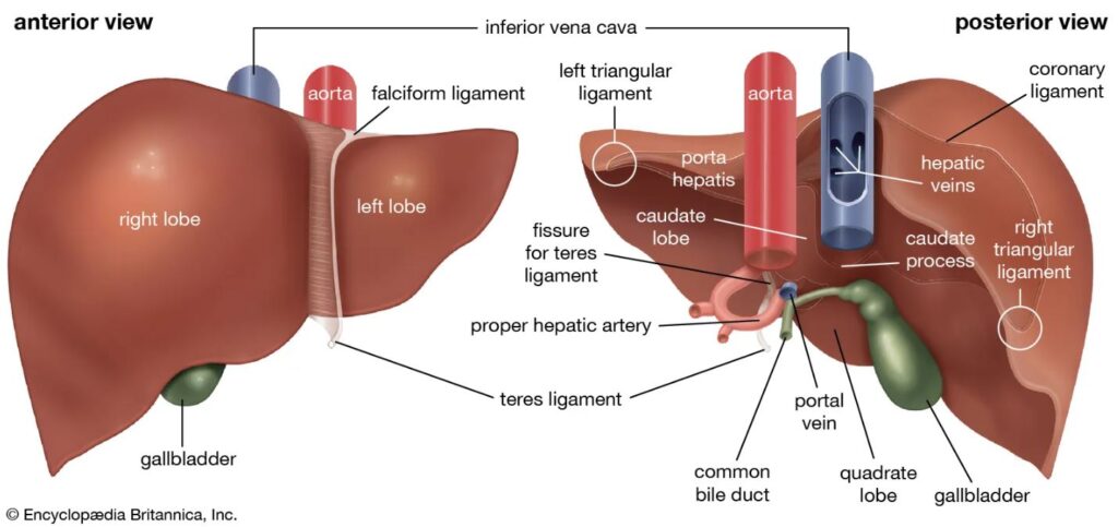
Image taken from Encyclopaedia Britannica, Inc.
Appearance of CT Liver - Late Arterial Phase (LAP) Images
Appearance of CT Liver - Portal Venous Phase (PVP) Images
Examination Overview
Protocol Structure
00_Liver3Phase (Adult)
-
- Topogram
- Non Contrast (Above diaphragm to the ischial rami)
Bolus Tracking
-
- Pre Monitoring
- (At the level of diaphragm)
- Pre Monitoring
Contrast
-
- Monitoring
- (At the level of diaphragm)
- Contrast triggering at the abdominal aorta
- Triggered when achieve 100HU
- Liver LAP
- (above diaphragm to the end of liver)
- Venous Phase
- (above diaphragm to the ischial rami)
- Delayed 5 Minutes (optional)
- Liver (above diaphragm to the end of liver)
- Full abdomen (above diaphragm to the ischial rami)
- Monitoring
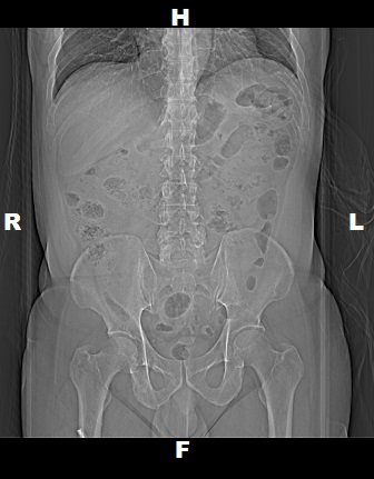
Topogram
- Position the patient in head first supine position.
- Align the patient in Mid-Sagittal plane of the table.
- Position the transverse laser light beam at the level of mid of sternum to start the topogram.
Topogram Parameters
- Topogram length: 512 mm
- Slice: 0.6 mm
- Scanning direction: Craniocoudal
- Tube position: Top
- Stop the topogram scanning when the scanning reach / pass over the inferior ischial ramus.
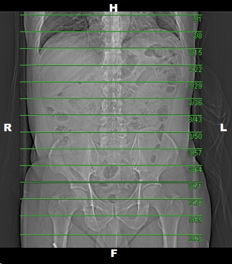
Non Contrast
- Plan the Scan FOV (SFOV) box at topogram image.
- Set the top line at the level of upper diaphragm.
- Set the bottom line at the level of inferior ischial ramus.
- Ensure the lateral line to cover patient’s body outline.
- Remind the patient before scanning as the breathing instruction will be given.
Scanning Parameters
- kV: 100 kV
- mAs: Tube Current Modulation (TCM)
- Scanning Direction: Craniocaudal
- Scan Delay: 4 s
- Slice: 5.0mm
- Image Comment: Pre-Contrast
- Pitch: 0.6
- Quality Reference mAs : 230
Reconstruction of Liver Non Contrast
Contrast
Type of contrast used:
-
- Non-ionic iodinated contrast media
- 300 I mg/mol
Needle Placement Test:
-
- Flow Rate: 3.5 ml/sec
- Volume of Normal Saline: 15 ml
Contrast Injection:
-
- Volume of Contrast Media:
- 100 ml (normal body type)
- Volume of Normal Saline: 50 ml
- Volume of Contrast Media:
Injector setup for Normal Body Size
Bolus Tracking
Pre Monitoring
- Set the scanning line at the level of diaphragm.
Monitoring
- Ensure the scanning line from Pre-Monitoring is at the level of diaphragm.
- Ensure the lateral line to cover patient’s body outline.
- Draw ‘Triggering ROI’ on Abdominal Aorta (left-hand click on Siemens CT console).
- Set:
- Delay: 10 seconds
- HU to triggered : 100HU
Post Contrast Scan Planning
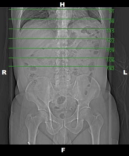
Liver LAP
- Plan the Scan FOV (SFOV) box at topogram image.
- Set the top line at the level upper diaphragm.
- Set the bottom line at the level of end of liver.
- Ensure the lateral line to cover patient’s body outline.
- Remind the patient before scanning as the breathing instruction will be given.
- Delay: 10 seconds (after Bolus Tracking).
Venous Phase
- Plan the Scan FOV (SFOV) box at topogram image.
- Set the top line at the level upper diaphragm.
- Set the bottom line at the level inferior ischial ramus.
- Ensure the lateral line to cover patient’s body outline.
- Remind the patient before scanning as the breathing instruction will be given.
- Delay: 25 seconds (after Liver LAP).
Reconstruction of Liver LAP
Reconstruction of Venous Phase
Delayed 5 Minutes (Optional)
- Liver
- Plan the Scan FOV (SFOV) box at topogram image
- Set the top line at the level of above diaphragm.
- Set the bottom line at the level of end of liver.
- Remind the patient before scanning as the breathing instruction will be given.
- Full abdomen
- Plan the Scan FOV (SFOV) box at topogram image
- Set the top line at the level of above diaphragm.
- Set the bottom line at the level of inferior ischial ramus.
- Remind the patient before scanning as the breathing instruction will be given.
- Ensure the lateral line to cover patient’s body outline.
Reconstruction of Delayed
Multiplanar Reconstruction (MPR)
Coronal LAP IV
- Image Thickness: 3.0 mm
- Number of Image: 19
- Coverage: Anterior to Posterior of abdomen
Coronal PVP IV
- Image Thickness: 3.0 mm
- Number of Image: 19
- Coverage: Anterior to Posterior of abdomen
Series of Images Send to PACS
- Topogram
- Non Contrast 5.0 B30f
- Non Contrast 1.0 B20f
- LAP 1.0 B20f
- LAP 5.0 B30f
- Venous Phase 5.0 B30f
- Venous Phase 1.0 B20f
- Delayed 15 Min 5.0 B30f
- Delayed 15 Min 1.0 B20f
- Patient Protocol
- COR LAP IV
- COR PVP IV


