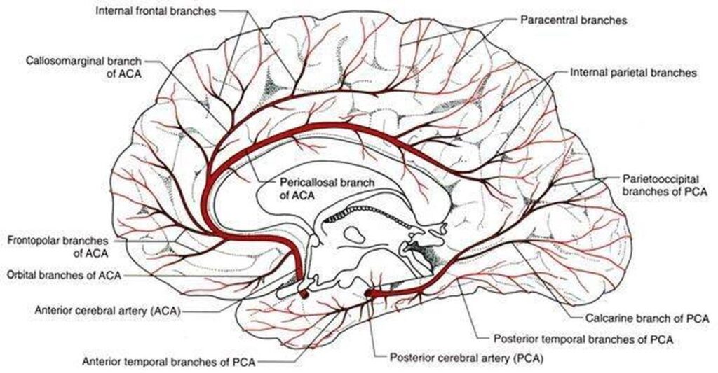
Image taken from Healthiack.com
00_NeuroDSACT (Adult)
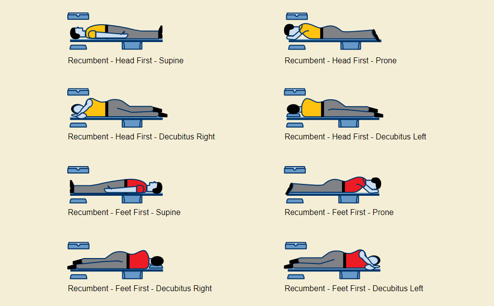
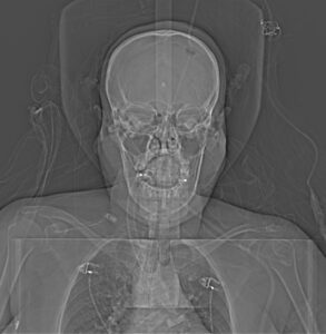
Topogram (AP)
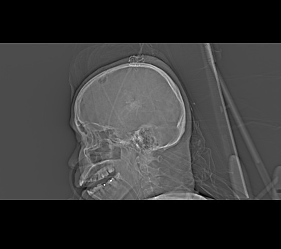
Topogram (Lateral)
Type of contrast used:
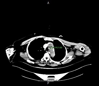
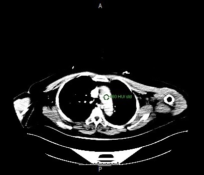
Needle Placement Test:
Contrast Injection:
N/A
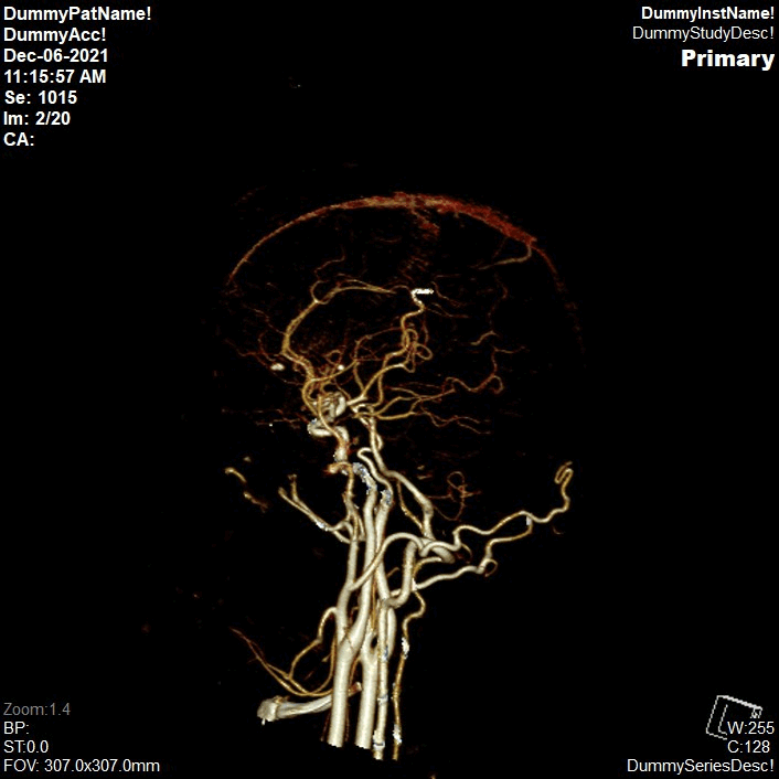
Volume Rendering Technique
Open with ‘CT neuro DSA’.
Rotate and punch.Select ‘Edit Bones’.Locate and mark the area that was cut along the vessel.Open ‘Range Tools’ choose ‘Radial Range’
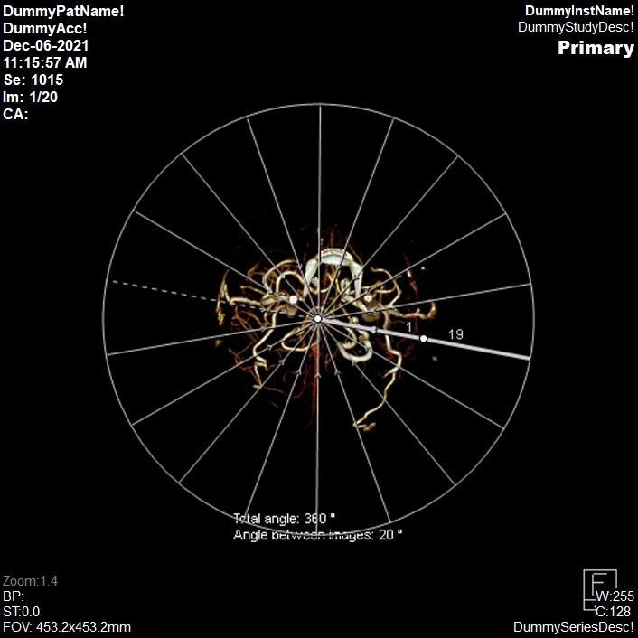
Radial Range:Number of images = 19 (lock)Angle between images= 19
Orientation:Start from AP view. Then click ‘Start’Save as VRT CTA Brain
Enter the destination URL
Or link to existing content