Image taken from Radiology Expert
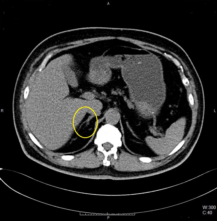
Right Adrenal Gland
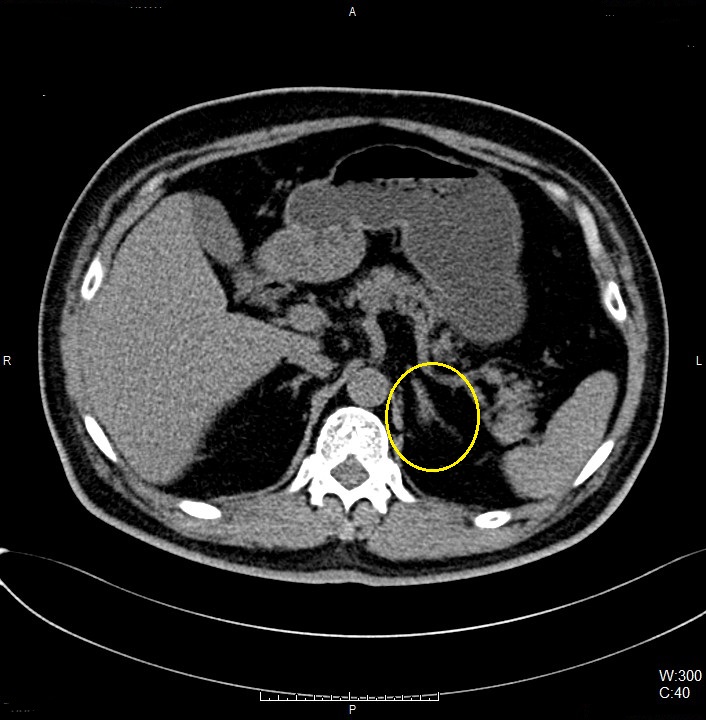
Left Adrenal Gland
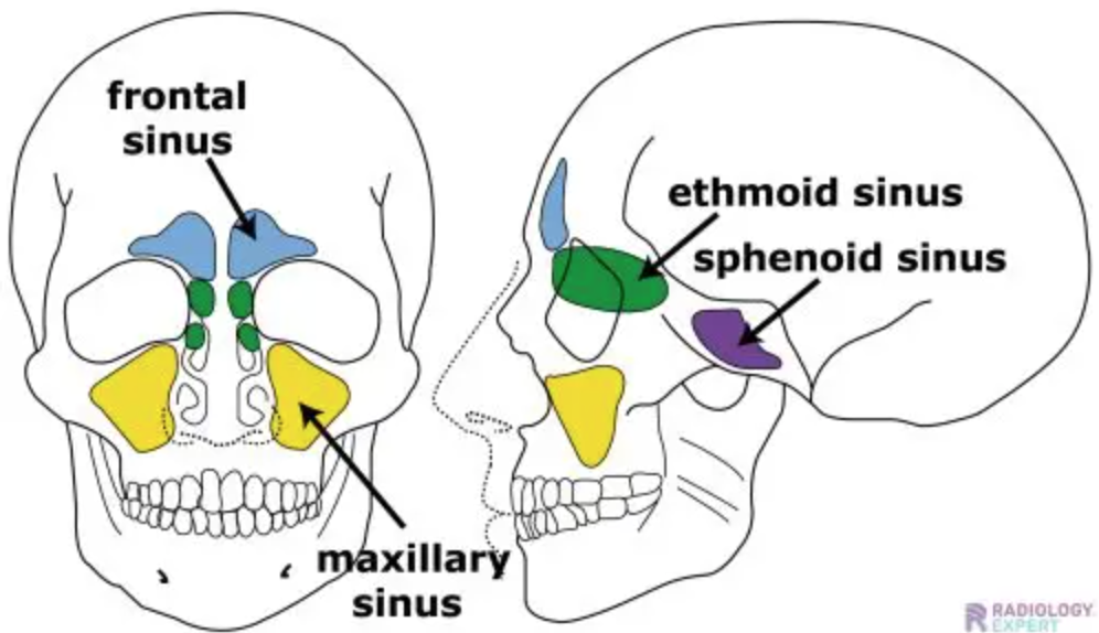
00_Sinus (Adult)
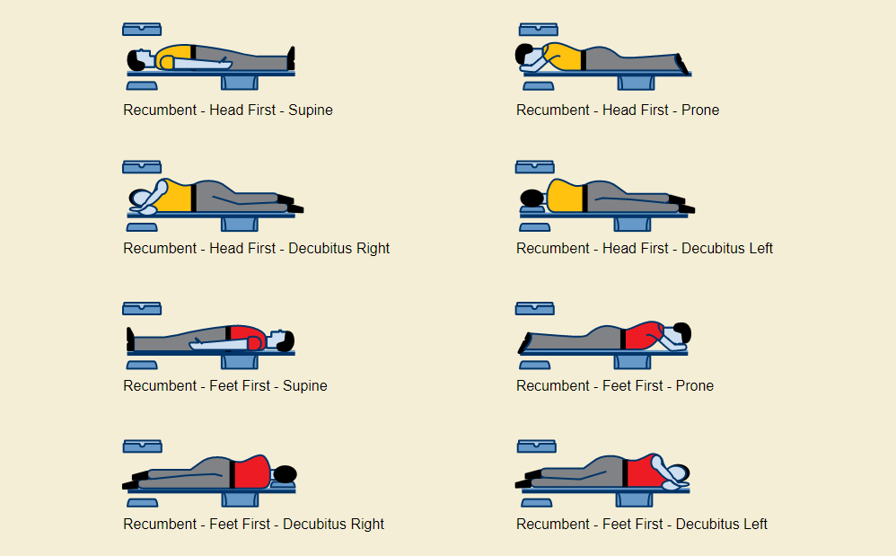
MPR must be process IF the scanning structure is asymmetrical in AXIAL image.
Enter the destination URL
Or link to existing content