Anatomy of Paranasal Sinus (PNS)
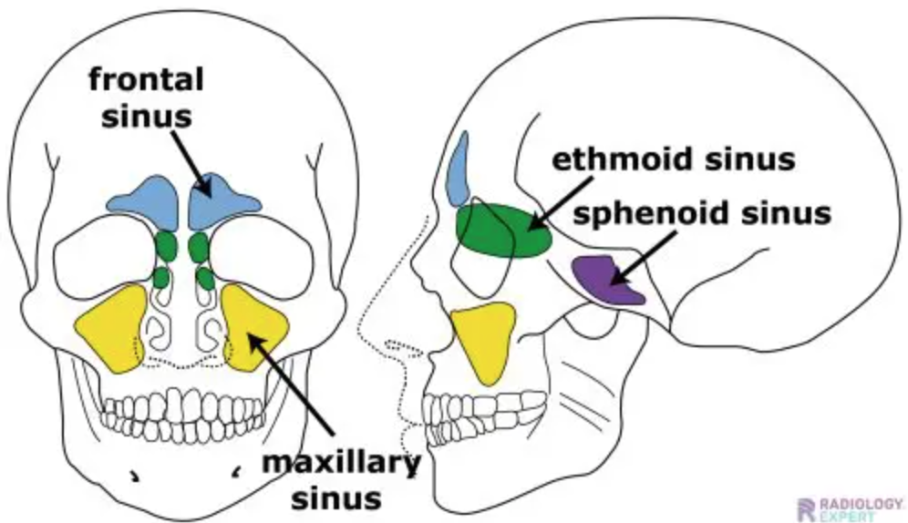
Image taken from Radiology Expert
Appearance of Paranasal Sinuses in CT Scan
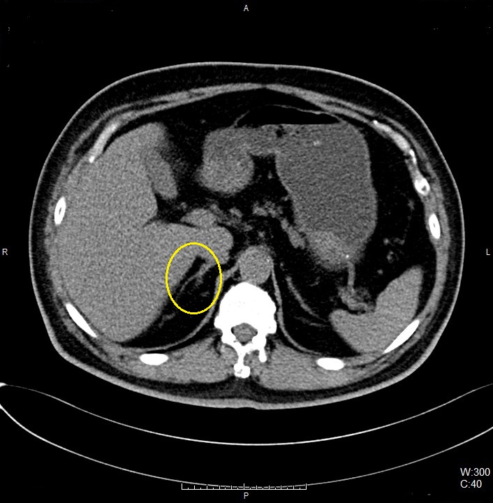
Right Adrenal Gland
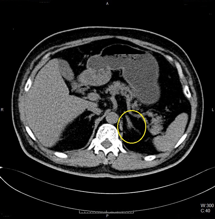
Left Adrenal Gland
Examination Overview
Protocol Structure
00_Sinus_for_IGS (Adult)
- Topogram
- Sinus
Topogram
- Position the patient in head first supine position.
- Place the patient’s head in designated head rest.
- Align the patient’s head in Mid-Sagittal plane of the table.
- Position the transverse laser light beam at the level of patient’s vertex of skull to start the head topogram.
Patient Orientation Registry in System
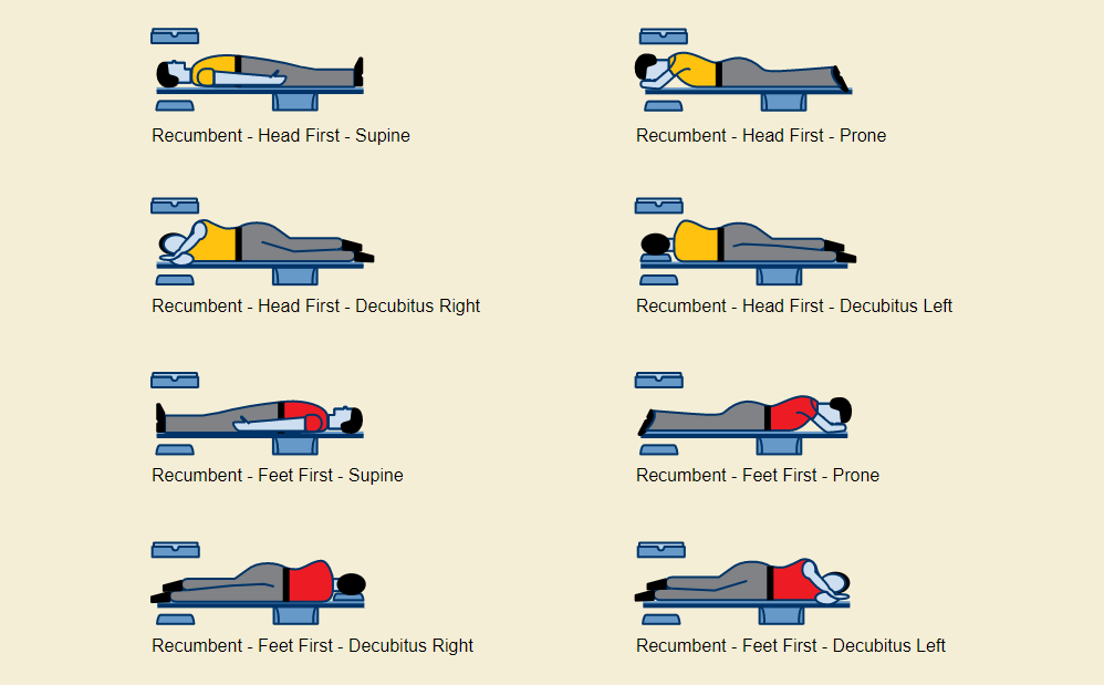
- Set the orientation patient in system: Head First – Supine
Topogram Parameters
- Topogram length: 256 cm
- Slice: 0.6 mm
- Scanning direction: Craniocoudal
- Tube position: Lateral
- Stop the topogram scanning when the scanning reach / pass over the hard palate / teeth.
Non Contrast
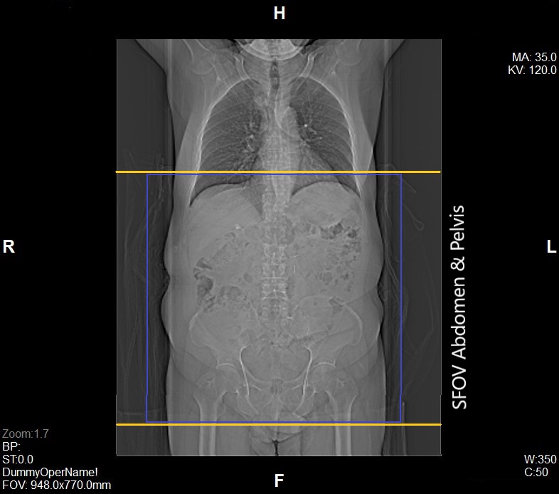
- Plan the Scan FOV (SFOV) box at topogram image
- Set the top line at the level above frontal sinus.
- Set the bottom line at the level below hard palate / teeth.
- Ensure the anterior and posterior lines to cover patient’s facial and occipital bones.
- Remind the patient before scanning as to keep still during scanning.
- Angulation of SFOV may be needed to ensure parallel of hard palate.
Scanning Parameters
- kVp:
- mAs: Tube Current Modulation (TCM)
- Scanning Direction: Craniocaudal
- Scan Delay: 4 s
- Slice:0.6
- Image Comment: Non Contrast
- Pitch: 0.6
Reconstruction of Non Contrast
Multiplanar Reconstruction (MPR)
Coronal Portal Venous Phase
- Image Thickness: 3.0 mm
- Number of Image: 19
- Coverage: Anterior to Posterior of abdomen
Series of Images Send to PACS
- Topogram
- Non Contrast 5.0 B30f
- Non Contrast 1.0 B20f
- PVP 5.0 B30f
- PVP 1.0 B20f
- Delayed 15 Min 5.0 B30f
- Delayed 15 Min 1.0 B20f
- Patient Protocol
- COR ST PVP


